Introduction
The Power Subsystem Monitor (PSM) for the Ground Autonomy Research Platform (GARP) is designed to provide measurement, configuration, and reporting capabilities for system power rails while accommodating evolving hardware configurations. The firmware architecture must tolerate unavailable rails at startup, expose a stable and versioned API to the Command and Data Handler (C&DH), and persist configuration data reliably across power cycles.
This article describes the requirements baseline, three representative use cases, and the resulting architectural decisions. These include a dual-core partition on the Raspberry Pi Pico 2 (RP2350), a CBOR-based API with schema-driven validation, a dual-bank nonvolatile storage strategy, and a fixed-width intercore messaging protocol. The emphasis is on determinism, interface stability, and predictable, reliable behavior.
GARP Article Series
The Ground Autonomy Research Platform (GARP) is a home-grown UGV designed and built to support independent learning of robotics and autonomy through a full stack from hardware to behavioral autonomy and HMI. To document the implementation of GARP, I’m capturing the process in a series of articles that I’ll link here as they’re completed:
GARP Article Map
- Motivations and Design of a UGV for Robotics Research
- GARP Power Subsystem
- GARP Mobility Subsystem
- Motor Selection
- Subsystem Design
- Motor Controller
- C&DH
- Design
- Alpha Implementation
- GARP E-Stop
- Design
- Alpha Implementation
Requirements
To begin shaping the scope of a PSM design, a few underpinning requirements are identified. Firstly, as a key tenet of GARP development, the PSM solution must support changing power rail configurations, ideally requiring minimal or no NRE1 firmware changes. This requirement predominantly falls into the “should” 2 category, with the exception that it strictly bars dependence on a measured 5 V rail for powering the PSM itself. Secondly, the firmware must accept that any measured rail may be unavailable or unstable at startup. Third, the PSM must allow querying from the Command and Data Handler (C&DH) and could be addressable from elsewhere in the GARP. This implies a defined transport interface and a stable API surface. The firmware can be developed with the C&DH in mind, but cannot be dependent on the C&DH for its operation. Finally, the PSM design should include traceability to reporting its own status. These items aside, to further develop the PSM’s requirements baseline, consider three use cases:
- A user, via the web UI running on the C&DH, queries the voltage and current on each connected power rail in succession, repeatedly; These values are displayed in the web UI and additional values like power consumption are displayed.
- A health subroutine monitors values measured by the PSM to determine if any values are outside of nominal levels.
- A user, via the web UI, changes the bias of a power rail as a hardware component in the PCB is introducing an incorrect bias in the measurement, as determined by manual measurement at the PSM’s input terminals.
Use Case 1: Measurement Querying
The first segment of this use case (“A user, via the web UI running on the C&DH, queries…”) implies that the PSM can be queried by a python application running on the C&DH. This introduces a requirement that there must be a protocol stack for communication between the PSM and C&DH, including the transport, data, and application layers.
The transport layer must provide for at least communication between the C&DH and PSM. It is foreseeable that it would be desirable to access values available via the PSM from system elements, such as from a safety or e-stop subsystem, but this could be achieved through a proxy by way of the C&DH. For example, a UART-based transport layer would allow communication (only) between the C&DH and PSM, whereas an ethernet-based solution would allow concurrent query from multiple points in the GARP. This will require both hardware support and software/driver support.
The data layer protocol will need to define a standardized format for sharing data objects. A bit-packing protocol could be defined specifically for the GARP’s PSM-C&DH connection, or (as will most likely be done), an existing protocol such as Protocol Buffers (protobuf) or CBOR could be used. This layer will also require encode/decode software support.
At the application layer, a dictionary of message formats for requests and responses will need to be defined. These will be defined in terms of the lexicon exposed by the data layer, i.e. by defining messages as collections of data layer primitives. This will require a schema defining an API, as well as the software necessary to pack and unpack these messages.
In general, any custom solutions will required versioned interfaces as a core principle of the GARP is that interfaces and arrangements are expected to change and should be extensible.
The second portion of this use case (“…queries the voltage and current on each connected power rail in succession, repeatedly;”) implies that queries are expressed in terms of power rails, and that both current and voltage can be sought for these rails. This then requires that power rails are referred to in terms of some power-rail-centric value (i.e. “the 80V rail” vice “the third connected rail”). Furthermore, while the availability of current and voltage measurements are dependent on hardware in the daughtercards, the PSM must at least support asking for them, even if the response is an error. Looking ahead, this will also promote hiding PSM internals like rail and signal indexes. The latter half of the above segment, “in succession, repeatedly”, implies that only a single rail measurement is requested at a time, although this does not preclude future APIs from including a “get all” query that returns all available measures in one message.
While the latter half of the use case (“These values are displayed in the web UI and additional values like power consumption are displayed”) falls into the scope of the web UI, the ability to derive additional values like power consumption does imply that units must be provided along with the measures. That is, the API must indicate what units measures are in (e.g.) volts vs millivolts.
Use Case 2: Comparison Against Nominal Values
The second use case implies that an unnamed health routine can monitor values measured by the PSM, and that these can be compared to nominal values. While the it is not specified that a health monitoring routing needs to run on the PSM, this is a rationale choice. Similarly, nominal values for each signal (e.g. current, voltage) on each rail will need to be available, and these will likely end up defined on and exposed by the PSM itself as these will change alongside PSM hardware changes.
The health monitoring feature is expected to be deferred to a subsequent version of the PSM as some characterization of the power rails’ performance will need to be made before flooding the communication between C&DH and PSM with warning and error messages. It is also expected that a future version could make a shift to a polling-based strategy, where internal states of the rails (perhaps filtered) are maintained on the PSM, and these states are reported when the PSM is queried.
Use Case 3: Runtime Calibration
Within the scope of the PSM, the third use case implies that it must be possible to adjust scaling and bias on measurements reported by the ADC(s). In line with the notion of querying the PSM from multiple GARP subsystems, these bias and scaling configuration values will likely need to be stored on the PSM itself. While unstated, it would be beneficial to have configuration changes survive GARP power cycles, as the alternative would be either frequent firmware updates during tuning, and/or PSM initialization by the C&DH at the start of each boot cycle. This would likely be achieved by use of nonvolatile memory (NVM) on the PSM.
Finally, this also implies exposure of configuration query and change messages via the PSM API.
Design Assumptions
Several design assumptions anchor the solution. Whereas requirements shape the potential design space, these assumptions reduce its manifold by making selections amongst several options, but care must be taken as these assumptions risk “painting oneself into a corner”.
The first design assumption made for the PSM is that a Raspberry Pi Pico2 (RP2350) will be used. This is effectively carried over from the hardware design choice to use a Raspberry Pi Pico2 with the RP2350 microcontroller, but is largely driven by the low cost of the Pico2, having a number on-hand, and success using them in the GARP motorcontrollers. Similarly to the motor controllers, the PSM will use both cores, with one hosting a communication controller (CC), and the second hosting an ADC controller (AC). Intercore queues will be used to send requests, measurements, and other data between the cores.
The second design assumption is that concise binary object representation (CBOR) will be used as the data layer encoding. CBOR provides a compact, structured, self-describing binary representation well suited to configuration maps while remaining transport-agnostic. Use of CBOR in the context of the PSM is discussed in more detail in the Design section below.
Design
Beyond the assumptions above, the PSM design will be developed in an iterative style starting at the highest layers of abstraction and driving downward into the most explicit layers. To this end, starting with the top-level architecture of the PSM and its interaction with the C&DH:
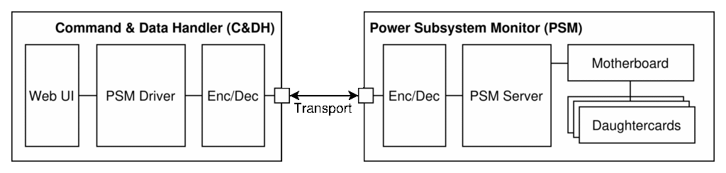
The primary functional of the web UI in the context of the PSM is to provide a simple, highly portable GUI for quickly disseminating system status and high-level performance metrics like voltages, currents, and power consumption. The PSM server and driver/client pairing will be designed to parse and assemble the application-layer messages used by the PSM, including queries of PSM rail measurements, responses with error reporting, and runtime configuration modification. The encoder/decoder layer will be used to interface the data layer to the transport layer and to reduce the NRE required if/when changing to a different transport layer. Beyond driver firmware implemented using the Pico C/C++ API, the motherboard and daughtercards are largely defined in hardware.
Below the top-level, there are several design decisions to be made. Loosely following a query flow from external communication to internal functionality, these are explored in order3:
- Transport Layer: What is the transport layer between C&DH and PSM?
- Data Layer: What data layer protocol is used between the C&DH and PSM?
- Stateful Configuration: How is a stateful configuration implemented on the PSM?
- Functionality by Core: How is functionality divided between the CC and AC cores?
- Intercore Communication: How is data shared between cores?
- API Definition: What messages does the API define?
- CBOR Library Selection: Which library or libraries should be used to add CBOR support?
Transport Layer
When choosing a transport layer, several options are available in the GARP. Currently the GARP’s C&DH hosts an ethernet network and a USB 3.0 hub, as well as UART, I2C, and SPI communications exposed by GPIO pins. Using a low-level communication protocol like UART or SPI will be expected to entail the production and use of less robust, custom cabling. Given that the PSM will be mounted on the power DIN rail next to several different voltage and current sources, this is expected to introduce more risk of EMI and/or accidental contact with power rails. The use of ethernet would likely provide the easiest means for exposing the PSM across the entire GARP data network, but would also require introducing an ethernet controller to the Pico2 microcontroller.
Use of USB as with the motor controllers is expected to provide an adequate solution. The Pico2 supports USB1.1, which is expected to introduce some latency, but likely not enough to impact the low-criticality needs of the web UI. Once a health monitoring functionality is introduced, or an e-stop or safety system dependent on timely power measurements is integrated, the adequacy of USB will need to be reevaluated. The bandwidth of USB 1.1 is also expected to be adequate, but should be characterized once implemented. The USB serial CDC built in to the Pico2 is bidirectional, which would support both synchronous request/response and asynchronous error reporting from the PSM. Robust cabling for USB is readily available.
As mentioned in the Design Assumptions section, CBOR will be used as the data layer protocol, which will require framing. The GARP PSM will use the frame structure shown in Figure 2 below:
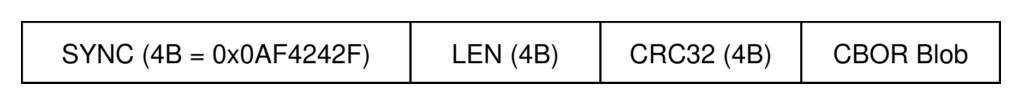
The byte blobs produced by a CBOR encoder will need to be framed before inserting it into a transport layer. Without framing, a dropped byte will be difficult to practically recover from. The framing to be used for the PSM’s transport consists of a synchronization/magic field, length, CRC, and the (variable-length) CBOR blob payload itself. The synchronization field significantly simplifies recovery from dropped bytes and by placing an ASCII newline (0x0A) simplifies wire debugging by starting each frame on a new line in a terminal window. The length field enables variable length CBOR blobs and therefore messages which will greatly improve the efficiency of communication between the C&DH and PSM given that a significant variety of message structures are expected. A CRC field is redundant given that USB already includes a CRC, but the four byte burden is small when considered in the context of potentially moving to another transport. The CBOR encoder will produce a byte blob that is an application envelope extended to define various semantically explicit messages. The application envelope and these various messages are described in the API Definition section.
Data Layer
As mentioned in the Design Assumptions section, CBOR will be used as the data layer protocol. While likely overkill for this application, CBOR will provide plenty of headroom as the types and arrangements of data transferred between the C&DH and PSM evolve.
CBOR is a binary serialization format standardized in RFC 8949. It encodes structured data models such as maps, arrays, integers, and strings, which aligns well with the query-response communications expected for the PSM. Furthermore, CBOR uses a binary encoding that is significantly smaller than JSON, and integer and small map encodings are particularly efficient. CBOR is self-describing at the type level meaning that the type and byte lengths of individual data objects do not need to be manually included, and makes assembling messages from different data types very low-lift. CBOR will require explicit framing, but is independent of transport layer, and will provide for easy changes of transport layer in the future. However, the parsing complexity of CBOR is greater than a fixed binary layout, and wire debugging is more complex than if using e.g. JSON.
This said, CBOR is a good choice for the PSM’s data layer as it supports structured, evolving message schemas with deterministic encoding, enabling forward compatibility and integrity validation without binding the system to a specific transport. Furtermore, CBOR has a broad set of support libraries and packages across C and Python. As an aside, CBOR reminds me of protobuf, and I’ll be using the PSM’s development as a pilot project to explore CBOR and its ecosystem.
Stateful Configuration
The PSM configuration will include fields like per-rail bias and scaling. The introduction of a stateful configuration introduces a few design questions:
- Location: Where to store the configuration?
- Content: What configuration parameters need to be stored?
- Format: In what format will the configuration data be stored?
- Functionality: What functionality needs to be implemented?
Location: As alluded to earlier, the configuration will be stored on the PSM itself. While it would be possible to store this on an external component like the C&DH, this would entail the C&DH initializing the PSM each time the PSM power cycles, and would also mean that all GARP components querying the PSM would need to use the C&DH as a proxy server to apply the measurement scaling and biases. Within the boundary of the PSM there are at least two options for storage; In the firmware itself, or in nonvolatile memory (NVM). Hardcoding configuration values in the firmware itself would require frequent reflashing during tuning of the PSM’s configuration, but would allow much faster access to values than if storing in NVM. That said, loading the configuration from NVM during PSM initialization and maintaining it in memory should be acceptable as the configuration data size is not expected to be significant.
Content: The next question revolves around what information needs to be stored. For the initial version of the PSM, the prior discussion of requirements and hardware design imply the following values need to be available for each daughtercard:
- Moniker: A brief, unique human-readable name for referencing the rail
- Scale and Bias: Scale and bias factors for applying a linear fit of measured values to actuals
- Signal Types: The types of the two signals per daughtercard (e.g. voltage and current)
- Nominals: Minimum and maximum nominal values for the two signals per daughtercard
- Enabled: A boolean indicating if the rail is enabled (e.g. is a daughtercard installed in this slot?)
Format: Given that CBOR is being used for the data layer of communication between the PSM and C&DH, and that is produces binary blobs, there are efficiencies in using the same encoder and decoder for storing configuration in NVM. The variable size of CBOR blobs does however introduce a need for framing in storage as the NVM will (erase and) write on 4 KB sectors. Using the fields defined above, the configuration data stored in NVM and its estimated4 size is:
| Field | Type | Default | Quantity | Total Size |
|---|---|---|---|---|
| Moniker | char[16] | “UNDEFINEDx” | 8 (1 per rail) | 128 B |
| Scale | float | 1.0 | 16 (2 signals per 8 rails) | 64 B |
| Bias | float | 0.0 | 16 (2 signals per 8 rails) | 64 B |
| Signal Types | uint8 | 0: UNDEF | 16 (2 signals per 8 rails) | 16 B |
| Nom. Min. | float | 0.0 | 16 (2 signals per 8 rails) | 64 B |
| Nom. Max. | float | 0.0 | 16 (2 signals per 8 rails) | 64 B |
| Enabled | bool | false | 16 (2 signals per 8 rails) | 16 B |
| Total | 416 B |
The Pico2 is produced with a 4 MB (RP2350-external) QSPI flash chip which dwarfs the <512 bytes needed for configuration from Table 1. The Pico’s C SDK allows erasing on 4 KB sectors, meaning the configuration framing will need to consume a full 4 KB5 The configuration framing to be used on the PSM is shown in Figure 3.
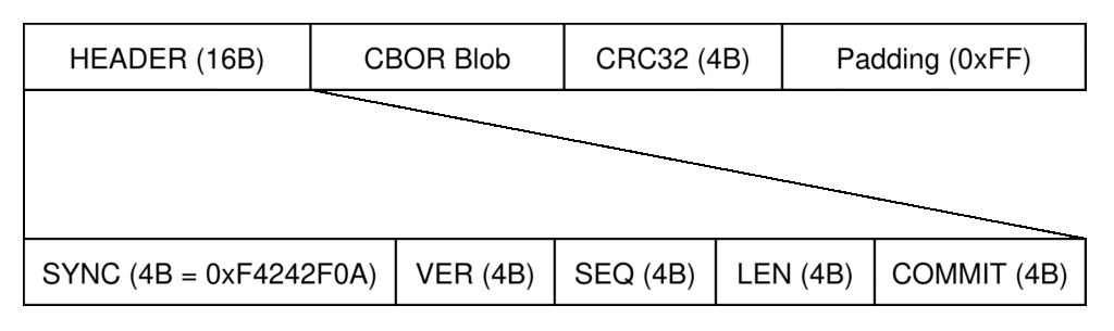
The configure framing will preface the CBOR blob with a header field and append a CRC of the blob itself, and pad to the requisite 4 KB length. The header itself will hold fields for a synchronization field as well as a configuration storage format version, a length field capturing the length of the CBOR blob in bytes, and a sequence value used in a dual-bank access strategy as discussed next.
Functionality: The minimum functionality required to support the PSM’s stateful configuration is fairly simple, comprised of basic load-from and save-to NVM functions, and the API additions are not terribly complicated. This said, to enable resilience in the GARP where errors and unplanned power cycling are expected, a dual-bank storage scheme will be used.
Rather than updating data in place, the dual-bank approach maintains two independent copies of the same dataset. At any time, one bank is considered the active, known-good copy, while the second bank is reserved for updates. When new data needs to be saved, it is written completely to the inactive bank and validated before becoming active. Only after the new copy has been successfully written and verified does the system switch over to it. This arrangement ensures that a valid configuration is always available. If power is lost or a reset occurs during an update, the previously active bank remains untouched and can be safely used on the next boot. On startup, the system examines both banks and selects the most recent valid one based on embedded integrity checks and the header’s sequence field. While the dual-bank design requires additional memory and more complex update logic, it provides strong protection against data corruption and simplifies recovery behavior. These properties make it particularly well suited for embedded systems like the PSM, where configuration integrity and predictable startup behavior are critical. Given that each configuration block will only consume 4 KB of a 4 MB flash memory, the dual-bank approach offers a robust and maintainable solution for persistent storage, balancing reliability with long-term flexibility as system requirements evolve.
Functionality by Core
As a design assumption, the RP2350’s two cores will be used for a communication controller (CC) and ADC controller (AC). To help identify the functionality required and to which core it is allocated, consider the basic query sequence diagram of Figure 4:
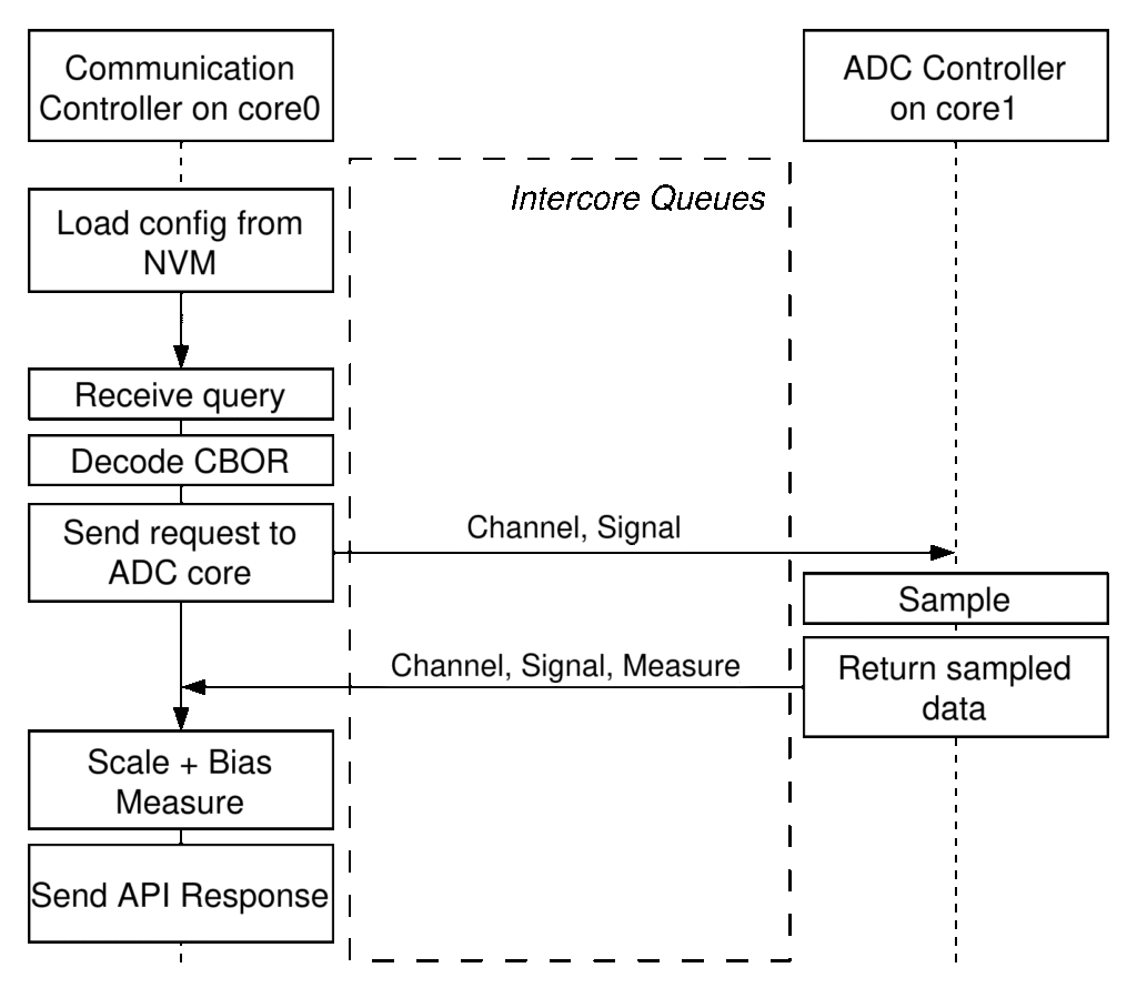
Figure 4 illustrates separation of responsibilities across cores, intercore queue communication, and the flow of an external API request through ADC sampling and ultimately to response generation. The sequence begins with the CC loading configuration from NVM during initialization. The CC then waits until it receives a query at which point it unpacks the API message, decodes the CBOR payload, and crafts a measurement task to send to the AC. The AC receives the measurement task, executes the sampling operation, and crafts a response message which it pushes to the CC. The CC then completes the process by applying scaling and biasing operations, encoding and framing the measurement, and sending it back to the requester. Completion of scaling and biasing operations on the CC core keeps all (mutable) NVM configuration on the CC and avoids the need to deconflict NVM access across cores. Furthermore, as the MCP3008 ADCs used on the PSM’s motherboard do not require any initialization, the AC configuration is hard-coded into the firmware. This includes hardware-defined configuration like pin numbers, but also software elements like SPI clock frequency.
Intercore Communication
The use of both cores on the RP2350, and in particular the trading of tasks and responses across the intercore boundary creates a need for an intercore communication protocol. While CBOR could be used here, it a) is significantly more complicated than necessary, and b) produces variable-length blobs which could complicate trading data across the Pico SDK-provided (fixed size) intercore queues. Given the simplicity of the task and response messages, a byte-packed protocol will be used as depicted in Figure 5.
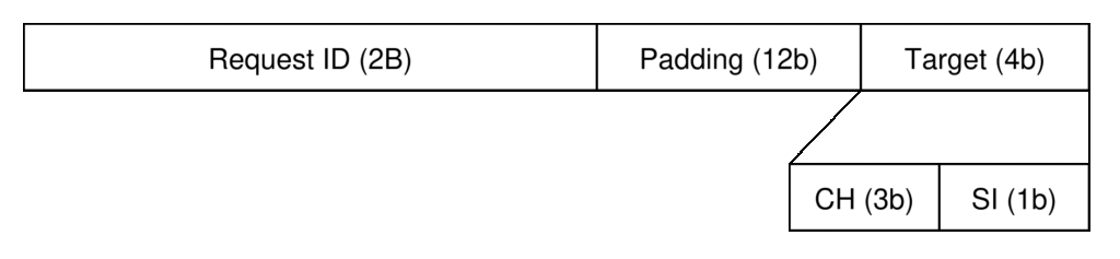
The intercore request (or task) message specifies the channel and signal to be measured by the ADC. Inherent to this is that the CC will parse the incoming request in terms of a rail moniker and voltage or current measurement, and use the PSM configuration to translate these specifications into a target for the AC, in terms of channel number (i.e. rail or daughtercard) and signal number on that daughtercard (e.g. voltage or current). The PSM API will assign a locally unique request ID to the incoming request which will be carried through the measurement task and into the associated API response. For the initial version of the PSM, the ID will be the same used in the external API, but in future versions a mapping of external-to-internal identifiers could be used for additional flexibility. The measurement response frame is shown in Figure 6.
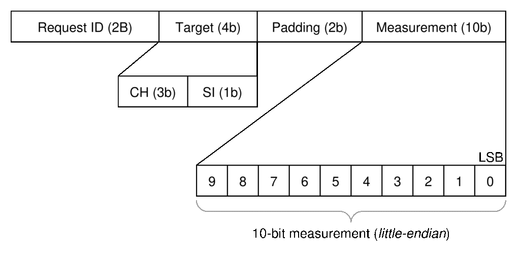
The intercore measurement response message includes the original request ID and 4-bit target (channel and signal numbers), and appends the ADC measurement. With this format, all messages are traceable back to an originating request in support of a queuing system, should future versions of the PSM demonstrate a need.
In summary, the intercore messages can be assembled and parsed with the pseudo-functions in Table 2:
| Message Type | Assembly | Parsing |
|---|---|---|
| Task Message | TM = (I<<8) + S + (C<<1) | I = (TM & 0xFF FF 00 00) >> 16 |
| Response Message | RM = (I<<16) + (C<<13) + (S<<12) + M | I = (RM & 0xFF FF 00 00) >> 16 |
API Definition
The PSM API defines the protocol that the C&DH will use to communicate with the PSM. CBOR, the data layer below it, defines the primitives that are the building blocks of the API’s messages. The API then becomes a collection of message formats and standardized workflows. The PSM’s API will use a request and response format for the majority of its communications, with future versions of the PSM expected to implement unidirectional messages like heartbeats and error reports. This leaves the message definitions.
The set of messages that will be implemented in the first version of the PSM are:
- GetAvailableConfigurationRequest
- GetAvailableConfigurationResponse
- GetAvailableMeasurementsRequest
- GetAvailableMeasurementsResponse
- GetConfigurationRequest
- GetConfigurationResponse
- GetMeasurementRequest
- GetMeasurementResponse
- SetConfigurationRequest
- SetConfigurationResponse
These functions will support getting the available configuration parameters and measurements (i.e. rails and signals), getting the current configuration and measurement values, and setting configuration parameters. All of the messages will be an extension of a common ApplicationEnvelope message format that includes the common API version, sequence, and flags fields, with message type and payload fields that are defined by the individual message types. The API version is used to denote the API-wide version, with updates batched in stable releases. The sequence field will be incremented but will not be used in the initial version of the PSM API, with the intent that it can be used in the future to support debugging communication with the C&DH and heartbeat signals. Similarly the flags field will be included, but ignored in the initial version of the PSM API. Looking ahead, the messages will be specified in concise data definition language (CDDL) format in the GARP PSM API repository.
CBOR Library Selection
With the design outlined above, a few notes on implementation are included here. In particular, a brief comparison of several CBOR libraries is presented, as well as the integration of selected libraries in the GARP Web UI, GARP PSM, and GARP PSM API projects is discussed.
The CBOR support libraries considered herein are:
- zcbor: A CDDL-driven CBOR code generator and lightweight C runtime designed for deterministic, schema-enforced messaging in embedded systems.
- tinyCBOR: A small, portable C library providing manual CBOR encoding and decoding with a low footprint but no schema or code generation support.
- libcbor: A flexible C CBOR implementation using a dynamic, DOM-style API suited to host applications rather than constrained embedded targets.
- cbor2: A widely used pure-Python CBOR encoder/decoder optimized for ease of integration in host-side tools and applications.
- QCBOR: A security-focused embedded C CBOR library emphasizing robust, defensive decoding without schema-driven code generation.
In selecting a CBOR library, the decision becomes a combination of feature checklists and architectural posture: flexibility or determinism shape how interfaces evolve and how rigorously message contracts are enforced, runtime dynamism or compile-time guarantees impact where correctness is discovered and how failures manifest, and tooling convenience or firmware discipline drive how tightly resource usage and long-term maintainability are controlled. To rack-and-stack the options and ultimately select options for use on the GARP, they can be examined through four lenses: C and Python support, encoder/decoder completeness, schema validation, and embedded suitability, including in the context of dynamic memory use.
zcbor takes a schema-first stance. It provides a C runtime encoder and decoder, generated directly from CDDL definitions, and includes python-based CLI tooling for validation. Its distinguishing feature is schema-driven development: the CDDL file is the contract, and C types plus encode/decode functions are generated from that contract. This moves accuracy beyond convention and into compile-time enforcement. For embedded platforms, this makes memory usage predictable, makes heap allocation optional, and message structure drift is addressed at build time, not runtime. Unfortunately, encoding and decoding in Python is not supported so it is likely not a good option for use on the web UI/client side.
TinyCBOR provides both C encoding and decoding in a compact, portable package, but without schema validation or code generation. It does not provide Python support. Message structure is defined implicitly in application code, and validation is manual. The library is well suited to embedded systems as the footprint is small and dynamic memory use is minimal, but schema accuracy must be maintained manually. It enables CBOR, but does not enforce a schema-defined contract.
libcbor also supports C encoding and decoding, but adopts a DOM-style, dynamically allocated tree model. It does not provide built-in schema validation or CDDL integration, nor does it include Python support. While flexible and expressive, its reliance on dynamic memory can make it risky for resource-constrained embedded systems. It is more naturally aligned with Linux host tools, gateways, or diagnostic utilities where memory overhead is acceptable and runtime inspection is valuable.
On the Python side, cbor2 provides a mature encoder and decoder for Python applications. It has no C implementation and does not enforce schema validation internally, though its implementation in Python enables easy integration with external validation workflows. It is not suitable for microcontroller firmware, but is a good option for host-side tooling, bridges, and test harnesses. When paired with a schema-driven embedded implementation, it can form a pragmatic division of roles and responsibilities: deterministic C on the embedded side, and flexible Python on the C&DH/web UI side.
Finally, QCBOR offers both C encoding and decoding with a strong emphasis on defensive parsing and robustness. It does not provide Python bindings or schema-driven code generation. It is embedded-friendly and avoids heavy dynamic allocation, positioning it well for security-sensitive IoT systems. However, like TinyCBOR, message structure enforcement remains an application-level responsibility rather than a schema-enforced contract.
Given these factors, the PSM API will use zcbor encode/decode on the Pico2/PSM side, and cbor2 on the C&DH/web UI side. On the PSM itself, zcbor will be used to validate CDDL-defined messages in continuous integration (CI) and autogenerate encoder and decoder code in a C library within the PSM API repository. That encode/decode library will be used for both API processing and generation of CBOR byte blobs for configuration storage in NVM. On the C&DH side, the cbor2 Python package will be used to encode and decode messages in the backend of the GARP web UI.
Summary
The PSM design translates a small set of operational requirements into a structured firmware architecture with defined boundaries and predictable behavior. By partitioning responsibilities across cores on the Raspberry Pi Pico 2, adopting schema-defined CBOR messaging, and implementing dual-bank nonvolatile storage, the system addresses measurement, configuration, and persistence in a cohesive manner. Versioned APIs, fixed-width intercore messaging, and configuration traceability reduce coupling and support incremental evolution. Collectively, these decisions establish a stable baseline for future extensions such as health monitoring, alternative transport options, and expanded measurement capabilities without requiring fundamental architectural changes.
- NRE: Non-recurring engineering
- MoSCoW (“must”, “should”, “could”, “won’t”) priority scale
- This order is only very loosely based on a query flow, and only generally moves from most abstract to least. In reality this order is defined by design dependencies and is the fruit of design hindsight
- Neglecting CBOR overhead
- This is not strictly true- the configuration could consume a smaller space and this blackboard could be manually managed in software, but the flash space is not expected to be so precious as to warrant this. Framing in separate 4 KB sectors is also justified in the dual-bank scheme discussed in the next section.