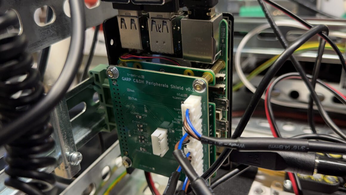
This article describes the first version of a small I/O shield for GARP’s Raspberry Pi 5 Command and Data Handler (C&DH). The board replaces individual connections to the Pi’s 40-pin GPIO header with four connectors for the motor-controller UARTs and a connector for a future I²C IMU. The primary goal was practical: retain the UART connections I had already brought up while making them easier to connect, trace, and keep connected inside the C&DH enclosure.
Initial wiring
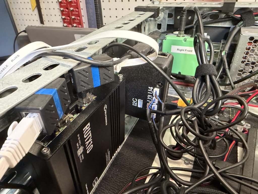
During early prototyping, I connected the motor controllers to the GPIO header using hook-up wires and Dupont connectors. This was sufficient to get the UART links running, but the connectors came loose often enough to interfere with debugging. Reconnecting a wire meant tracing it back to the right header pin, and the pins associated with one UART were not necessarily adjacent. With four controllers connected, a fair number of wires were sticking out above the C&DH.
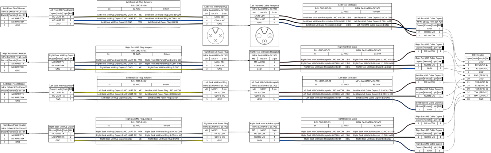
I made wire-harness diagrams to trace TX, RX, and ground from each motor controller through its panel connector and cable to the C&DH header. These diagrams gave me a way to identify the physical path when reconnecting or debugging a link. They did not, however, stop the Dupont connectors from coming loose or reduce the number of wires at the header.
I also wanted to put the C&DH in an enclosure without leaving the 40-pin header exposed. The problem had become physical rather than documentary: I could record where the wires went, but I still needed a better way to make the connections. That pointed to a custom PCB.
Requirements and first revision
The immediate requirement was to preserve the four motor-controller UART connections already in use. I had an I²C IMU on hand, so I included an I²C connector as well, although that interface had not yet been brought up. The C&DH will ultimately need additional connections to the power subsystem monitor and the EStop safety coordinator. A UART expansion IC was a candidate for those channels, but I had not selected one and did not want to make that part of this first revision.
The resulting shield breaks out the Pi’s existing UART and I²C signals. I selected JST connectors because I had them on hand and they latch. Each three-pin UART connector carries TX, RX, and ground; hardware flow control was not introduced. The four-pin I²C connector carries 3.3 V power, ground, SDA, and SCL. This groups the signals needed for a given interface at one connector instead of spreading a motor-controller connection across the GPIO header.
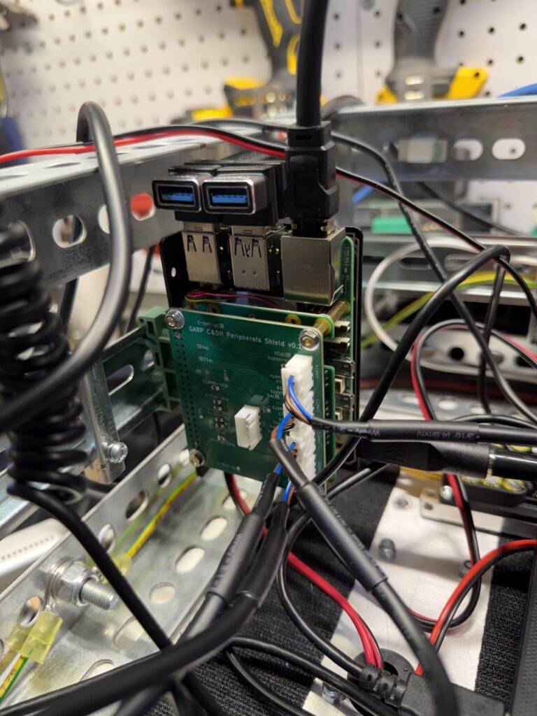
The shield plugs into the Pi’s 40-pin header through a connector on its underside; it does not create four new UART controllers. The board is labeled GARP C&DH Peripherals Shield v0.1, and the C&DH enclosure was designed around it. I did not spend much time optimizing the routing. The UART data rates were low enough for this layout, and there was enough board area to keep the routing straightforward.
The TPD2E2U06DCK was selected for ESD protection on the UART lines because one device protects both the TX and RX lines and its 1.5 pF typical capacitance also makes it suitable for the shield’s I²C signals, allowing me to use the same protection part at both types of connector. I placed the ESD ICs next to the UART and I²C connectors to provide a short path to ground. This decision was influenced by earlier CAN boards that stopped initializing after communication failures and by shocks I received while touching the robot when it was on blocks. Static discharge may have contributed to those failures, but the available troubleshooting did not establish the cause. Adding protection to the exposed signal lines was a precaution; I have not tested the shield’s ESD immunity.
I also considered an EEPROM for shield identification and automatic overlay selection. I deferred it to keep the first board focused on the connections that were already causing trouble.
UART configuration on the C&DH
The PCB organizes the physical connections, while the Raspberry Pi still needs software configuration to expose its UARTs. On the C&DH’s Ubuntu installation, boot configuration enables UART0, UART2, UART3, and UART4 through Device Tree overlays. Separate micro-ROS agents use the corresponding serial devices for the four motor controllers. A wheel’s physical connection to the shield determines which UART reaches that controller.
The motor controllers also expose USB serial connections for logging. Unlike the physical UART links, those USB connections can appear under different /dev/ttyACM* numbers depending on enumeration order. Udev rules give each log connection a stable alias based on the motor controller’s device ID and serial number. These aliases make the logs easier to identify; they are separate from the UART connections through the shield.
Integration checks
The v0.1 board was fabricated and installed in the C&DH. I checked the fit with the enclosure and used basic tug tests to confirm that the latching connectors held as needed. I then ran the standard GARP bring-up and used my ROS 2 Function Generator to send sinusoidal, ramp, and step-function command waveforms to all four wheels. The motor controllers responded, confirming that the installed shield supported the four communication paths in this setup.
This was an integration check, not a lifetime or ESD test. I have not yet used the I²C connector with the IMU. It did answer the immediate question: the shield fit the enclosure, the connectors stayed in place during the basic handling checks, and I could send commands through all four motor-controller connections.
Next steps
The I²C connection still needs to be used with the IMU. Additional channels for the power subsystem monitor and EStop safety coordinator remain a later design problem. I have considered a more substantial connector, such as Molex, but the JST connectors have not shown a need for replacement.
The deferred EEPROM also needs a more precise decision. Under Raspberry Pi’s HAT+ specification, an ID EEPROM carries the board’s identity and may name a Device Tree overlay. The overlay itself is not stored in the HAT+ EEPROM; the firmware loads the named file from the boot filesystem. Raspberry Pi OS keeps its overlays under /boot/firmware/overlays and invites HAT+ designers to submit new overlays to the Raspberry Pi Linux repository. The C&DH runs Ubuntu, whose Raspberry Pi boot assets include their own Device Trees and overlays. For automatic HAT+ configuration on this machine, the matching overlay would need to be available in Ubuntu’s boot assets, whether supplied by its distribution or installed and maintained separately. An EEPROM alone would not replace that work. For v0.1, I kept the existing explicit UART overlays and deferred HAT+ identification.
Summary
The first C&DH I/O shield replaced four sets of individual UART header wires with latching connectors on a board that fits inside the enclosure. Harness diagrams had helped me trace the original wiring, but did not solve its physical connection problems. The v0.1 board has passed fit and basic handling checks, and it has been used to send commands to all four motor controllers during GARP bring-up. The IMU connection, additional serial channels, and any automatic HAT+ identification remain later work.
References
- GARP Electrical Engineering — electrical design repository, including the C&DH I/O shield KiCad project, schematic, and PCB.
- GARP C&DH mobility notes — UART overlays, micro-ROS agents, and udev rules for the motor-controller logging ports.
- GARP Bringup — the robot bring-up referenced in the integration check.
- ROS 2 Function Generator — the command-waveform tool used for the four-wheel check
- Raspberry Pi HAT+ specification — ID EEPROM and Device Tree overlay requirements.
- Ubuntu Raspberry Pi boot assets — Ubuntu’s handling of Device Trees and overlays on Raspberry Pi.